The WS-79 is a radio built for Division 79, the next chapter of The Black Watchmen. The Black Watchmen is an alternate reality game on Steam, made by the studio Alice & Smith. In the game the player becomes an agent of a secret organisation. The WS-79 is the radio that agent uses.
This page explains what the radio does, how its case is made and which parts go into it. The parts are sold online and none of them needs soldering. Every program, guide and 3D file of the project is open on GitHub.
The radio
What the WS-79 looks like
The radio is drawn in 3D before it is built. Every size in the model comes from a real part: the two meters, the keypad, the microphone and the two bar screens. The case is a wedge with walnut sides. Its black face leans back toward the person who uses it.
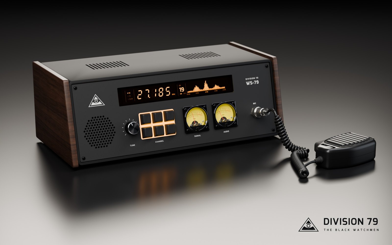
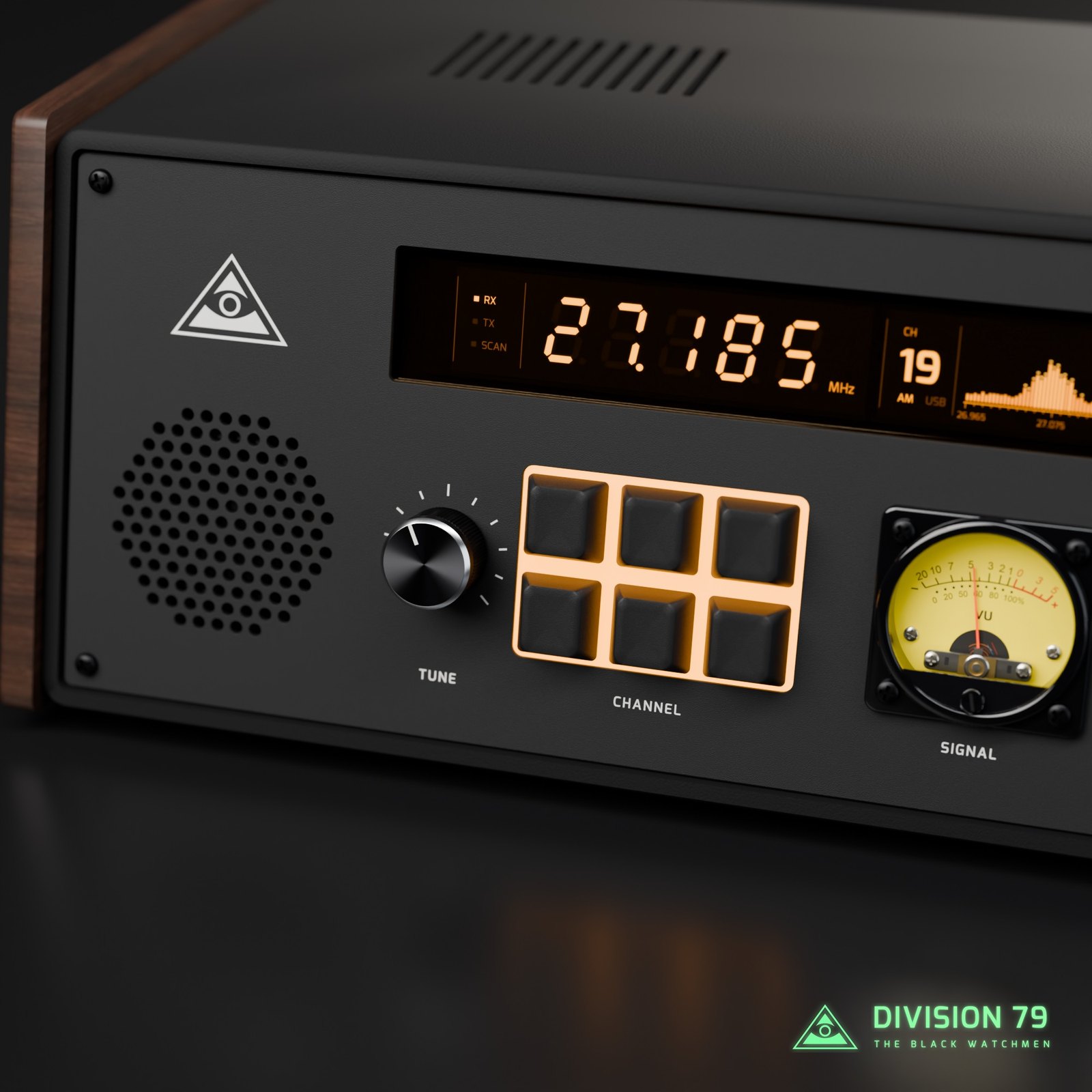
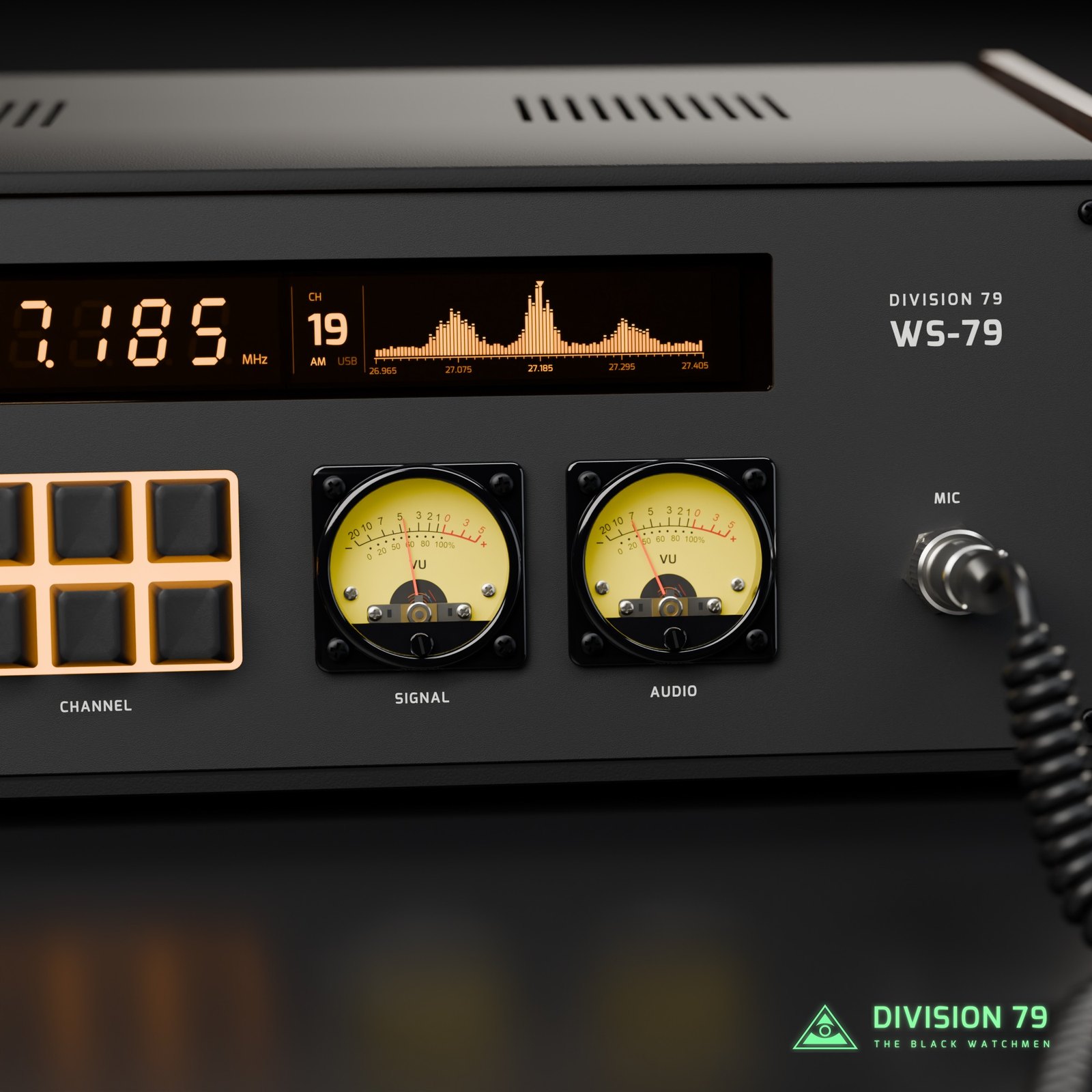
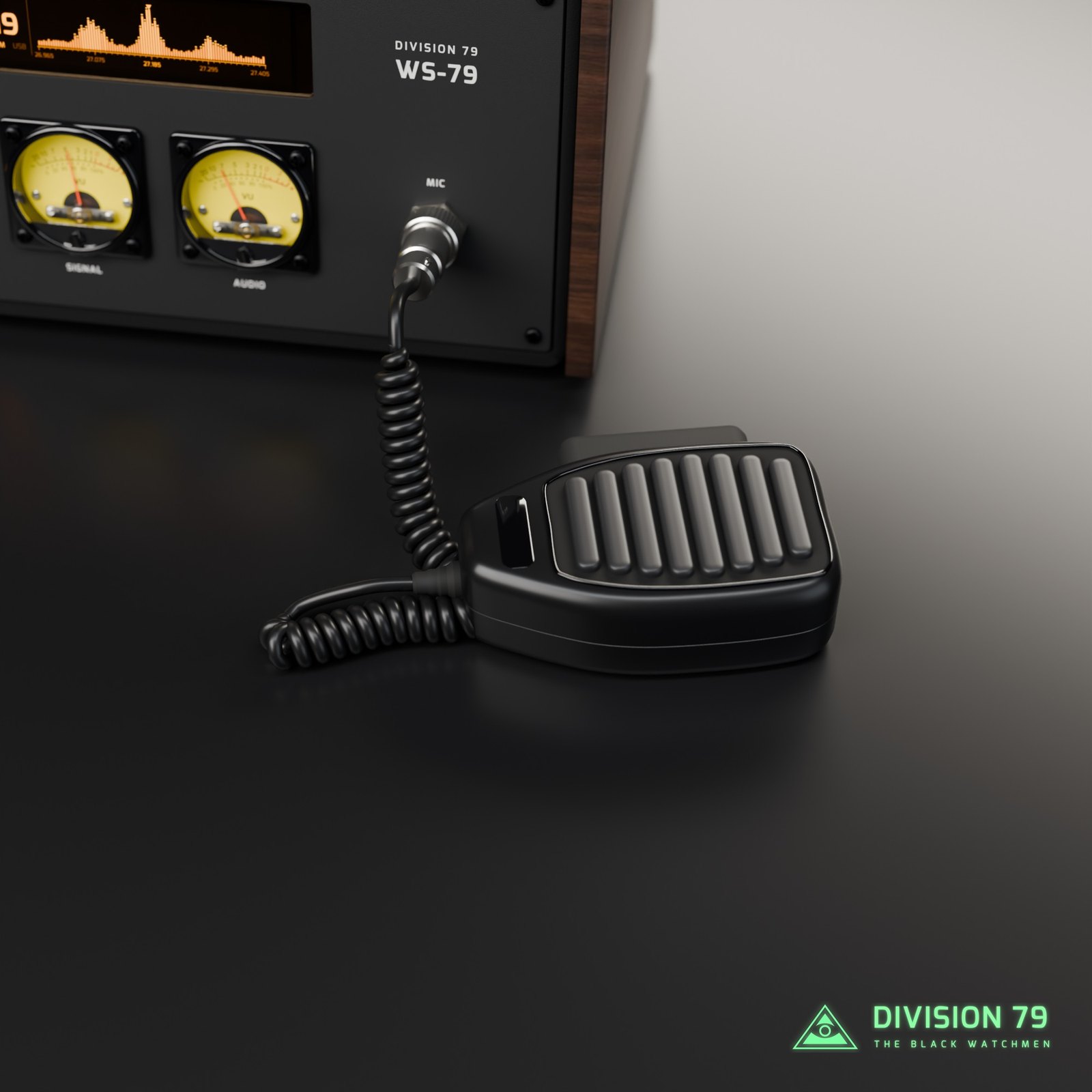
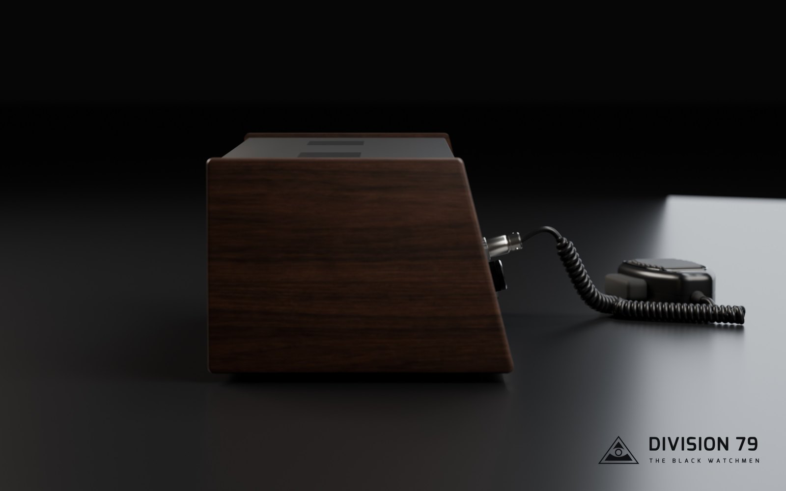
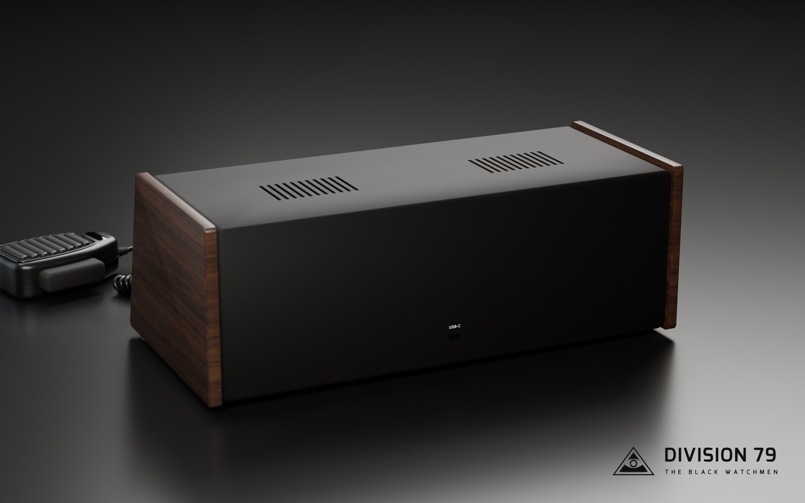
On the bench
What the radio does
The first bench test, filmed on 15 November 2026.
The radio turns files into sound. In the video it sends a text file and then a picture as a series of tones, the way amateur radio operators send pictures over the air. A phone running Stinger OS, the game's app, listens through its microphone and turns the tones back into the text and the picture.
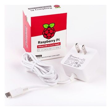
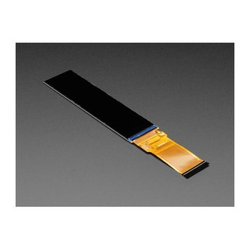
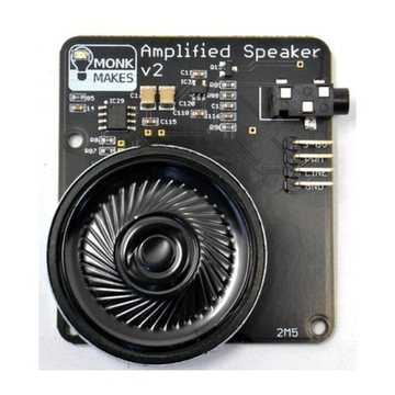
A Raspberry Pi runs the radio. A program written in Python plays the transmissions, reads the keys and the knob, and sends the frequency and the spectrum to the screens. Each screen has its own small board, which runs a second program in CircuitPython. A student who follows the project meets programming, sound, electronics and 3D design in one object.
The case
How the case is made
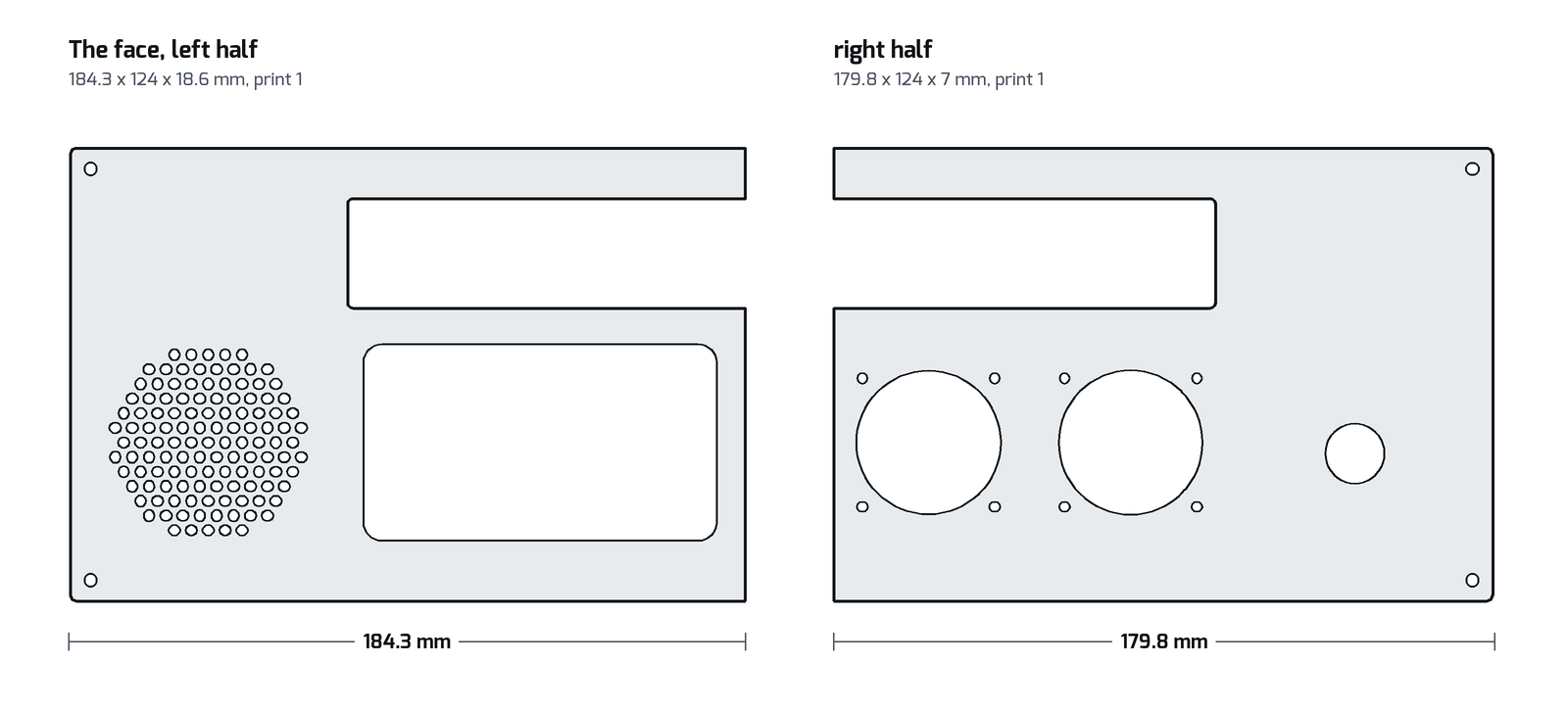
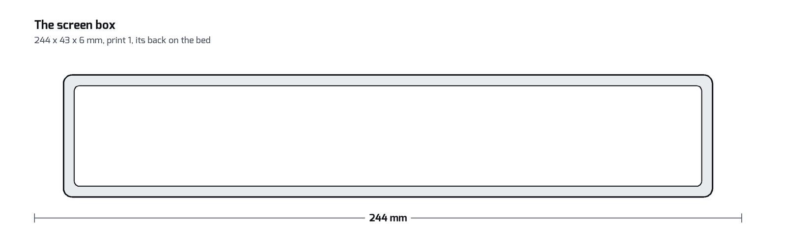
A 3D printer makes the face in black plastic. The openings for the screens, the keys, the meters and the speaker are part of the print. Posts printed on its back take screws, so every part is held by a screw and nothing is glued. A woodworker makes the two walnut sides.
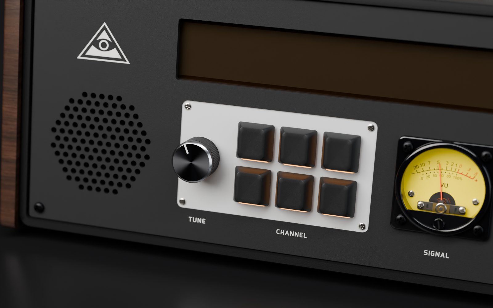
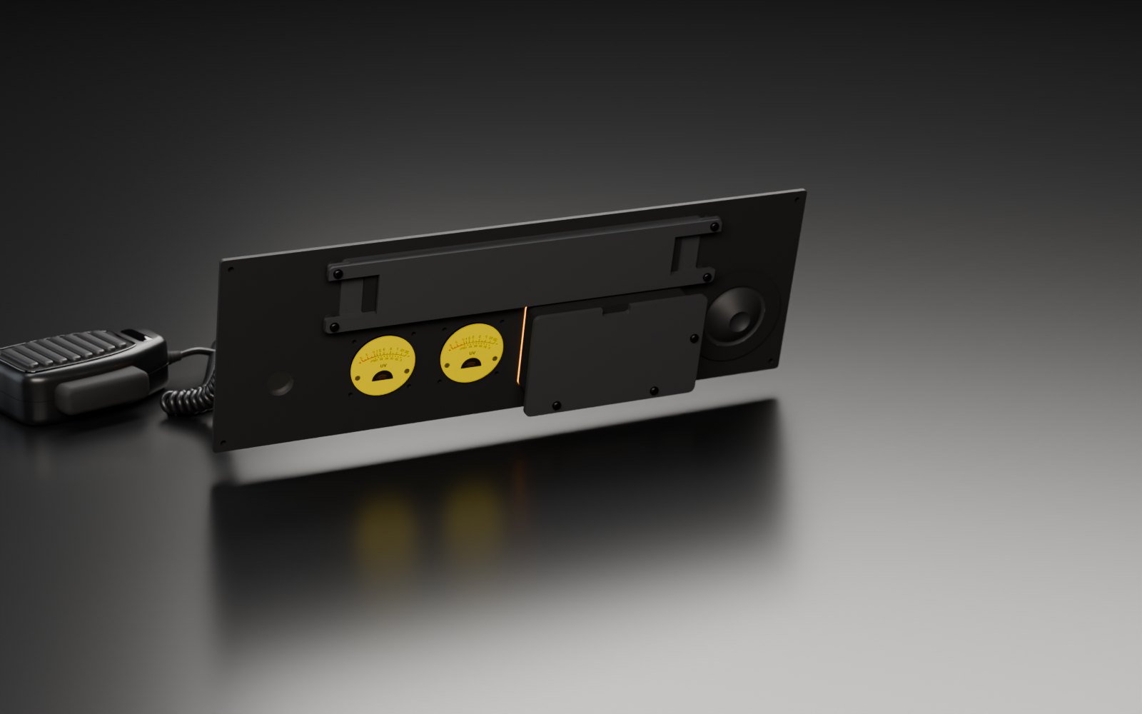
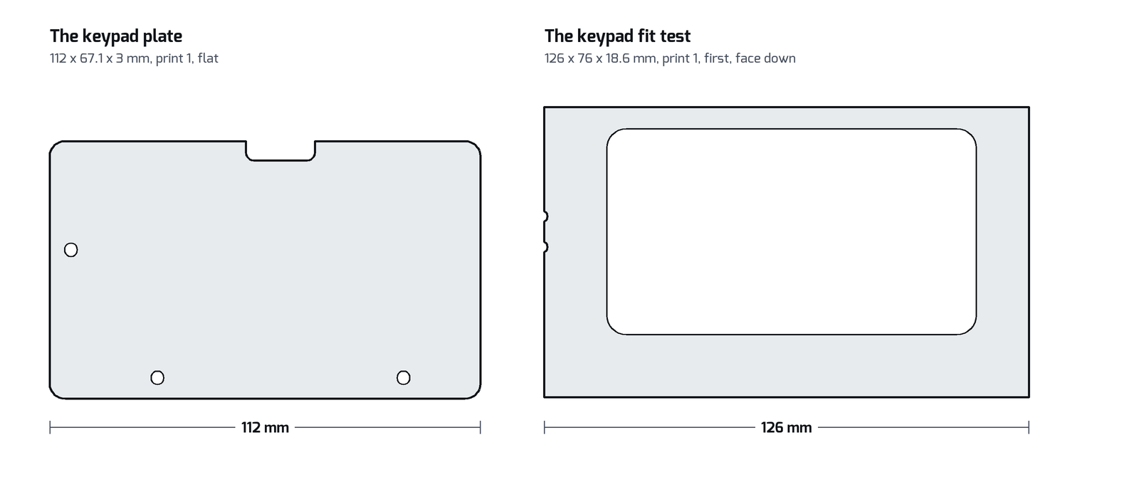
The face is 364 mm wide. A common printer has a bed of 256 mm, so the face is printed in two halves that join behind the window. The drawings below come straight from the print files.
The parts
22 parts with no soldering
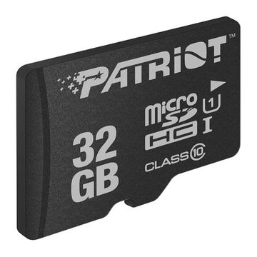
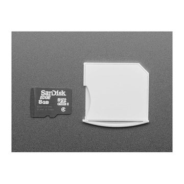
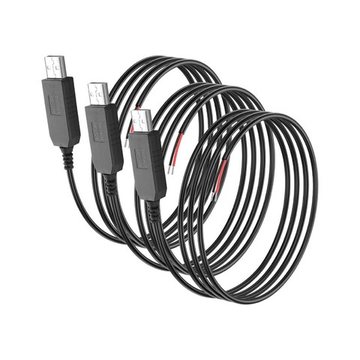
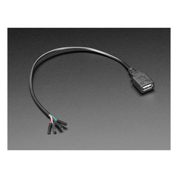
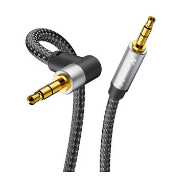
Each part plugs into the Raspberry Pi by USB or by a wire with a socket at each end. The parts are grouped below by the job they do in the radio.
The computer
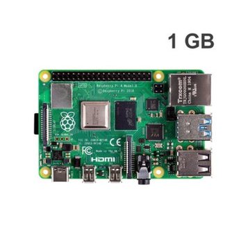 × 1
 × 1
 × 1
 × 1
The screens
 × 2
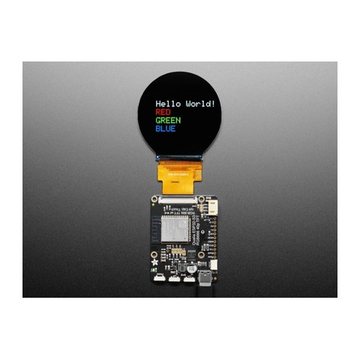 × 2
The controls and the meters
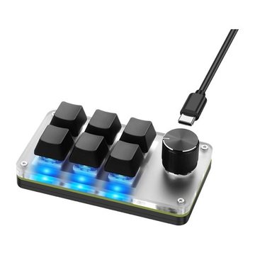 × 1
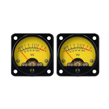 × 1 pair
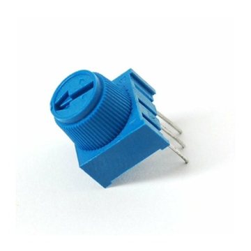 × 2
 × 1
 × 1
The sound
 × 1
 × 1
The microphone
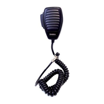 × 1
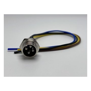 × 1
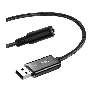 × 1
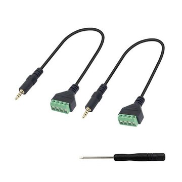 × 1
Cables and power
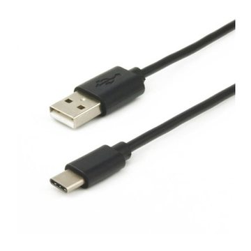 × 3
 × 1 strip of 20
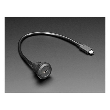 × 1
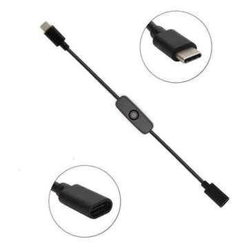 × 1
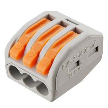 × 1 pack of 50
For the case
- Black PLA filament for the printer.
- Seven M3 screws: four hold the screen box and three hold the keypad.
- A sheet of 2 mm smoked acrylic in front of the screens.
- Two walnut sides.
The whole project
Open the WS-79 project on GitHub
The project page holds everything a class needs to follow it: the parts list with a sheet for each part, the wiring guide, the setup guide for the Raspberry Pi, the programs, the 3D model and the print files. Its licence lets a school use it and adapt it for a class.
github.com/Anashel-RPG/ws79-radioOpen the project